JUMO dTRON 16.1
Indice
The green indicator flashes '1999' or '9999'.
This signals that an over/underrange condition of the external setpoint has occurred.
This includes:
- probe break/short circuit
- setpoint outside the specified range (SCL, SCH)
- display overflow
- configuration in C111 is not correct
The red indicator flashes '1999' or '9999'.
If '1999' flashes, this means that either no measurable signal is present (probe break) or the configuration under C111 is incorrect.
1. Check the measurement signal (resistance measurement, current/voltage measurement), if necessary, define values using a signal source.
2. Check configuration code C111 (default setting Pt100, Chapter 7.1 of the Operating Instructions).
Input 1: Hardware modification between universal input and 0...10 V.
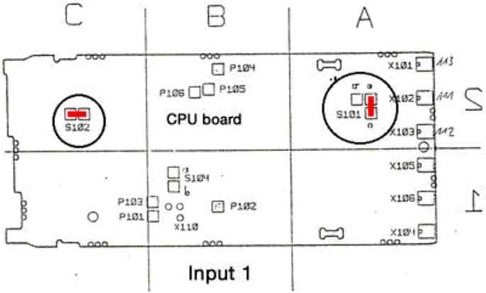
For the standard universal input (resistance thermometer, thermocouple, current), the solder bridges S101 and S102 on the CPU board are configured as follows:
- Solder bridge S101: a and b connected, a and c open
- Solder bridge S102: open
If input 1 is to operate with 0...10 V (other signals are then no longer possible!), the solder bridges on the CPU board must be changed as follows:
- Solder bridge S101: a and c connected, a and b open
- Solder bridge S102: closed
Bridge configuration for input signal 0...10V at input 1:

CPU board
The settings at the configuration level (C111, C112...) cannot be altered.
Cause: The configuration level was not called up via the parameter y.0
Can the dTRON 16.1 be configured from a PC?
A PC setup program for configuring the controller from a PC is available for the dTRON 16.1. As well as the PC program, JUMO Part No. 70/00400027, you will need an interface cable with a special adapter for the dTRON 16.1. The JUMO Part No. for the interface cable is 70/00400821.
Switch between current and voltage for the analog output.
The analog output (output 3) is an optional output and is not fitted in the standard instrument. If the output has been included in the order, then the output signal can be changed between current and voltage by means of solder links on the output board. The signal start 0 or 2 V, or 0 or 4 mA, is set at the configuration level C 114.
It can be seen from the type designation whether a dTRON 16.1 with an analog output has been supplied. Please refer to the operating instructions, chapter 2 “Identifying the instrument version”.
The following two solder links on the analog output board must be altered accordingly when changing between 53604884319/image_b8m5u9i5cp7b79mugijnfe2818/-FWEBP" width="400" height="257" style="float: none;" />
| Output signal range | Solder link S 602 (S1) | Solder link S 602 (S2) |
| 0/4 - 20 mA | open | open |
| 0/2 - 10 V | closed | closed |

analog output board
Which values are determined by auto-tuning and how long does auto-tuning take?
Depending on the selected controller type, the following parameters are determined through autotuning:
| Controller type | Parameter |
| 2-state controller ON/OFF function | Pb1, dt, rt, Cy1, df |
| 3-state controller | Pb1, Pb2, dt, rt, Cy1, Cy2, df |
| Proportional controller | Pb1, dt, rt, df |
As soon as autotuning is started from the “Exit“ key (hold down for 2 sec), the controller attempts to determine the time response of the process by applying step changes in the manipulating variable. Autotuning evaluates the development of the process value resulting from these changes in the manipulating variable and calculates the controller parameters. During autotuning, you will see “ tune “ flashing in the bottom display.
On termination of the autotuning procedure, “ tune “ ceases to flash.
The duration of the autotuning procedure depends on the time response of the controlled process. If the process reacts relatively quickly to the changes in manipulating variable, then autotuning may be over in a matter of seconds or minutes. With slow processes, autotuning may take half an hour or longer.
- ${title}${badge}


